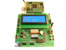
Current lead time on this product is 6 to 8 weeks.
Designed to be compatible with the 50-pin "H1" connector on virtually all "Adapt" products-- from the high-end Adapt9S12XEP100 all the way to the original Adapt11 running BUFFALO, introduced in 1995-- this is a versatile trainer!
The full-featured board includes light and temperature sensors, dual H-bridge motor driver circuit, LED bargraph display, DIP switch, audio transducer, Red-Green-Blue LED, and dual-axis joystick selector switch. Options include: a matrix keypad + encoder chip, various standard character LCDs (with or without LED backlight), and a USB interface. An added bonus is on-board socket strips designed to accept the popular XBee radio communication modules from Digi, enabling wireless networking (Zigbee, etc.). Two 8-bit microcontroller ports and five analog channels are brought out to socket strips for the user via ESD protection circuits, making them robust for lab use. The microcontroller's SPI pins are also brought out to a special connector for easy interfacing to SPI peripherals and soon-to-be-announced products.
Feature List:
- 10-segment LED bargraph
- audio transducer with driver circuit
- 8-position rocker style DIP switch
- pushbuttons provided for IRQ, XIRQ, Reset, and one port pin
- photocell
- linear temperature sensor
- linear potentiometer
- dual H-bridge motor driver circuit:
- drives two DC motors or one bipolar stepper motor
- pluggable terminal blocks for quick connect and disconnect
- separate input for motor supply voltage (up to 24VDC)
- indicator LEDs for each motor phase
- max. 600 mA per phase
- tri-color LED (red, green, blue) driven by three separate port lines can generate any color via PWM waveform
- dual-axis joystick selector switch
- use it for navigating a user interface on the LCD
- use it to control the positions of the two R/C servos
- Options:
- supports optional standard character LCD (in 4-bit mode)
- mounting holes for 4x16 and 4x20 displays
- plug and socket for matrix keypad and 74C922 encoder chip
- socket strips for adding an XBee or XBeePro radio module
- powered by on-board 3.3V regulator
- two 3-pin headers for plugging in R/C servos
- receptacle for optional USB2MCU interface module, providing USB interface to attached Adapt module
- supports powering entire trainer from USB port
- supports optional standard character LCD (in 4-bit mode)
General:
- can be used with virtually all "Adapt" series MCU cards, with near-100 % compatibility
- mirror-image pinout, plugs onto H1 connector of MCU card to form a planar configuration
- operates at 5V
Choosing Connector Options:
Since this card has a mirror-image pinout, it is intended for use in a planar configuration. That means if your MCU card has RA, RA1, FRA, or FRA1 connector option on H1, you should choose FRA, FRA1, RA, or RA1 for P1, respectively.
Customization is possible for volume or class-set orders. Please contact us to discuss.
Product Details
This product, called EVALH1, is part of the Adapt Modular Prototyping System (AMPS) pioneered by Technological Arts in 1995. Here's how it works: pick any Adapt module having the MCU you want to work with, and just plug it onto this evaluation/training board. Add any of the options you want (LCD, keypad + encoder chip, USB interface, XBee module, etc.) Here are some example combinations, showing order codes for each item (suggested connector options are shown, where applicable):
1. Adapt9S12DG128SM0 using CodeWarrior Development Suite for S12(X) via on-chip Serial Monitor.
- #AD9S12DG128SM0 (-RA1-RA1) microcontroller module with 9S12DG128 MCU
- #AMPS-EVALH1 (-FRA1)
- #LCD20X4-WB (4x20 LCD, blue background, white characters, LED-backlit)
- #LCDKIT1 mounting hardware for LCD module
- #74C922 keypad encoder chip
- #MK4X4 keypad
- #RC16FF06 ribbon cable for keypad
- #USB2MCU for USB interface
- 2 pcs. of #XB24-Z7CIT-004 radio module
- #USB2X for host radio module
- #UCA5MB6 (miniB USB cable)
- power it all from the host PC's USB port (via USB2MCU)
- download the free Special Edition of CodeWarrior from www.nxp.com (32K C code limit; unlimited assembler) or purchase the full edition from NXP
2. Adapt9S12C32 using CodeWarrior and Serial Monitor via ComPort
- #AD9S12C32M (-RA1) microcontroller module with 9S12C32 MCU
- #AMPS-EVALH1 (-FRA1)
- #LCD16X4 character LCD with 4 rows of 16 characters, non-backlit
- #LCDKIT1 mounting hardware for LCD
- #74C922 keypad encoder chip
- #MK4X4 keypad
- #RC16FF06 ribbon cable for keypad
- #DC9VRS (9VDC switching power supply)
- download the free Special Edition of CodeWarrior from www.nxp.com (32K C code limit; unlimited assembler)


