Product status: built to order (contact us)
Module Overview:
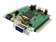
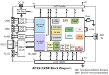
Implemented in an "AdaptS12" form factor board, Adapt9S12XDP512 is compatible with an entire range of application cards, prototyping cards, and backplanes, and usable with solderless breadboards ("proto boards"). The module includes the NXP/Freescale S12XDP512 MCU and all necessary support circuitry, as well as a 5-Volt regulator, RS232, RS485, and two CAN transceivers on-board. The flexible, modular design of the "Adapt" series of microcontroller modules makes them suitable for training, evaluation, development, prototyping, and volume applications.
MCU Overview:
An enhancement of the popular S12 family (and fully backward-compatible CPU), the S12X family utilizes the latest process technology. It boasts higher speed (40 MHz), more functionality, reduced power consumption and cost, and enhanced performance with the new XGATE RISC co-processor, on-chip memory-management, and DMA module.
MCU Features:
The MC9S12XDP512 combines a full suite of on-chip peripherals, including 512K bytes of Flash, 32K bytes of RAM, 4K bytes of EEPROM, six asynchronous serial communication interfaces (SCIs), three serial peripheral interfaces (SPIs), an 8-channel Input Capture/Output Compare enhanced capture timer, an 8-channel, 10-bit analog-to-digital converter, a 16-channel, 10-bit analog-to-digital converter, an 8-channel pulse-width modulator (PWM), five CAN 2.0A, B software compatible modules (MSCAN12), two I2C bus blocks, and a Periodic Interrupt Timer. The MC9S12XDP512 has full 16-bit data paths throughout. Note, however, that not all signals are brought out in the 112-pin version of the chip which is used on Adapt9S12X.
Summary of differences between the S12XD family and the S12 family:
• 40MHz operation
• 80MHz XGATE peripheral co-processor
• Extended CPU instruction set
• additional Condition Code Register
• Programmable eight level interrupt controller
• Enhanced Memory Management Controller
• New four channel Periodic Interrupt Timer
• Improved Enhanced Capture Timer with modulus prescaler options
• Non-multiplexed 8MB expanded memory bus (144-pin package only)
• New low-power RC trigger and fast recovery from STOP modes
• Decimal prescaler for Real Time Interrupt module
• Improved SCI featuring hardware bit manipulation for LIN
• Enhanced trigger source options for Analog to Digital Converters
• Amplitude controlled Pierce oscillator
• Wider and deeper debug module
Module Features:
- MC9S12XDP512 MCU (112-pin)
- 16 MHz crystal
- bus speed up to 40MHz (using on-chip PLL)
- accommodates optional user-supplied oscillator
- automotive-grade low-dropout 5V regulator
- 32K RAM
- 4K high-endurance EEPROM
- 512K high-endurance Flash
- independent Flash blocks permit execution from one block while programming/erasing another block
- fast in-circuit programming
- on-chip Serial Monitor for quick loading of user programs via uBug12JE multi-platform GUI
- program in C, BASIC, Forth, assembler, etc.
- Background Debug Module (BDM) fully supported for loading and debugging user code via a BDM pod
- universal 6-pin/10-pin BDM connectors support BDM pods from multiple vendors
- compatible with Freescale's CodeWarrior (requires supported BDM pod, such as our USBDMLT)
- RS232 transceivers provided for two SCI channels
- RS485 transceiver provided for a third SCI channel
- two physical-layer high-speed CAN transceivers (PCA82C250 or equivalent)
- one I2C interface
- 8-channel Input Capture/Output Compare Enhanced Capture Timer
- dual 8-channel 10-bit analog-to-digital converter subsystems
- 8-channel PWM subsystem
- periodic interrupt timer
- includes low-voltage inhibit reset circuit + reset button
- accommodates optional precision voltage reference chip for analog-to-digital converters
- 2.30" x 3.25" standard AdaptS12 form-factor card
- two 50-pin connectors (H1 and H2) bring out all I/O pins of the MCU
- all I/O pins on a 0.1" grid for easy interfacing to standard perfboard
- versatile I/O connector design for use with solderless breadboards, prototyping cards, or for easy embedding into your product
- stackable vertically or horizontally
- convenient corner mounting holes
- ideal development platform for all 9S12XD variants
What's included:
- assembled, tested module, pre-programmed with a Technological Arts adaptation of the Freescale Serial Monitor
- power cable assembly (#PCJ1-8)
- data sheets, manuals, and all other resources for this product can be found in the Resources section below
If you require mating connectors, browse Connectors in the Components category
Before you order...
This is an advanced product, for experienced users. You may wish to purchase a BDM pod such as our USBDMLT to assist you with product development.
All of our standard connector options are available for this board. The product photo above shows "RA1" connector on both H1 and H2. Make your choice of connector options before adding this item to your shopping cart. Otherwise, the board will be shipped without connectors on H1 and H2.
Here are a couple of ways you can use Adapt9S12XD:
- Flash-based code development using on-chip debug/monitor
With a 2K Flash-resident debug/monitor program, you'll be able to load your program into the remaining 510K Flash via the serial port using our uBug12JE graphical user interface for Windows/Mac/Linux. The entire 510K Flash can be programmed in under 30 seconds! To use the monitor for debugging or code-loading, just set the switch to LOAD. To run your standalone program thereafter, leave the switch at RUN. Your code runs from Flash, and interrupts are supported (via Flash-based pseudo vectors, since the monitor resides in the vector space of the MCU). A program you load into Flash this way will run every time you apply power or reset the board in Flash Mode.
- Flash-based code development using a BDM pod
If you want to take advantage of a more advanced development tool, the entire 512K Flash can be used, because the Flash-resident bootloader is no longer needed (therefore pseudo-vectors aren't required either). Make sure you get a BDM pod that supports XGATE (such as our USBDMLT). If you plan to use CodeWarrior, USBDMLT is the recommended pod (called "TBDML" in CW).
Resources
- Module Data Sheet, Schematic, App Notes, and code
- NXP S12XD web page
- uBug12JE: a free Java-based multi-platform GUI for working with the on-chip serial monitor (no BDM pod required)
- CodeWarrior C compiler/assembler for S12X from Freescale (the free Special Edition has 32K C code limit; unlimited assembler)
- Cosmic C Compiler
- QuantiPhi (Low-Level Driver Configuration and Generation Tool) for Simulink
- Compiler Build Tools
- Open Source Engine Management System at www.diyefi.org


